How to set up fire security system
Part 1 Laying Pipeline
1. Common pipeline material Electric tube pipe contains galvanized steel pipe, welded steel pipe, JDG steel pipe, KBG steel pipe and so on.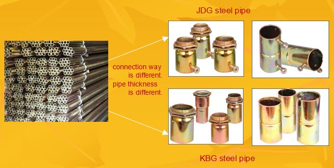
2. Wiring types the meaning of the various symbols labeld on common wire and cables
NH——Refractory,pass GB12666.6 refractory test;
ZR——Flame retardant,pass GB12666.5 bundle burning test
ZA/ZB/ZC——Flame retardant Class A / Class B / Class C
WD——Low smoke and halogen free
YJ——Cross – linked polyethylene insulation
V——PVC sheathed
S——Twisted pair
B——Single stranded hard line
R—-Single stranded soft line
K——Control Cable
P——With shield
For example: WDZA-KYJY-7*1.5——Low smoke halogen free flame retardant A grade XLPE double jacket 7 core 1.5mm2 control cable.
Common used wiring types: At least flame retardant wire and cable should be used for weak-current line and fire-resistant cable should be used for the power supply line of the fire alarm system.
alarm circuit——ZR-RVS-2*1.5, NH-RVS-2*1.5, NH-RYJS-2*1.5 etc.
alarm circuit trunk——ZR-RVS-2*2.5, NH-RVS-2*2.5, NH-RYJS-2*2.5
24VDC power line——ZR-BV-2*2.5, NH-BV-2*2.5, NH-BYJ-2*2.5 etc.
24VDC power line trunk——ZR-BV-2*4.0, NH-BV-2*4.0, NH-BYJ-2*4.0
multi-line control circuit——ZR-KVV-N*1.5, NH-KVV-N*1.5 etc.
broadcast line——ZR-RV-2*1.5, ZR-BV-2*1.5, ZR-RVVP-4*1.5
telephone line——ZR-RVS-2*1.5, ZR-RVVP-2*1.5, NH-RVVP-2*1.5 open
pump line——ZR-BV-2*1.5, ZR-RV-2*1.5, NH-BYJ-2*1.5 etc.
fire hydrant open pump feedback line——ZR-RV-4*1.5, NH-BYJ-4*1.5, ZR-KVV-2*1.5
network line——ZR-RVS-2*1.5, ZR-RVV-4*1.5, cat5 etc.
3. Sharing tube principle principle: Different systems, different voltage levels, different current types of lines, should not be laid in the same tube or in the same slot.
For example: strong-current line and weak-current line should not share tube broadcast line and other line should not share tube
telephone line and other line should not share tube network communication line and other line should not share tube alarm circuit line and 24V power line should not share tube alarm circuit line and open pump line should not share tube multi-line control line and alarm circuit line, 24V power line should not share tube
Part 2 Equipment Installation
1. Circuit types
There are ring circuit, T circuit, and mixed circuit
2-wire is generally used for the circuit, some equipment requires ring circuit
Every circuit (loop) can have 100 point, 200 point, or 324 point etc. 10~20% margin should be left for each circuit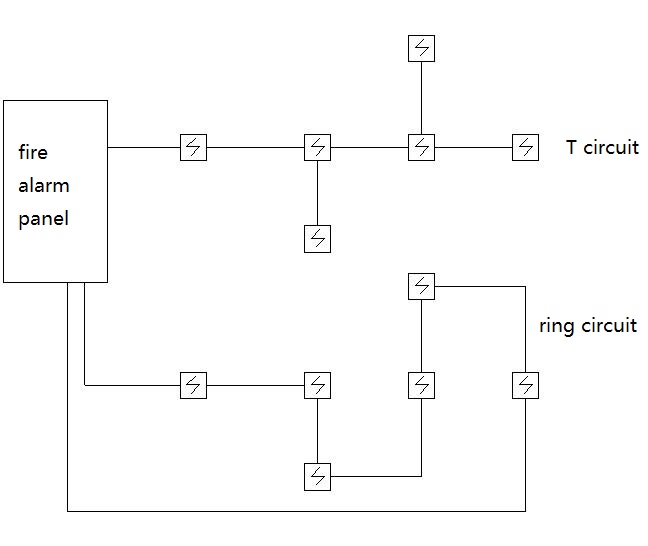
2. Detectors
detector types:
point type(Photoelectric smoke, ion smoke, temperature, complex, UV flame, combustible gas, dual band, etc.)
line type(Infrared beam, recoverable / unrecoverable temperature sensing cable, air sampling, distributed fiber, light section, etc.)
conventional detector(non-coded)intelligent detector(coded)
installation location caution:
point type(distance between ceiling, roof, wall and height from the ground) line type(laying way, distance between the roof , installation spacing) distance between other equipment and beam plate
3. Modules
surveillance module (input module, surveillance relay)
control module(output module, smoke exhaust relay)
combination module (input/output module, dual input module, dual output module, other combination module)
manual alarm button and fire hydrant button(coded/non-coded, telephone jack)
detector module(alarm relay, bus access module)
short circuit isolation module
relay module(switch module)
Installation location: in module box
4. Fire display panel
types of fire display panels:
1)LED display
2) analog display panel
3)LCD display
installation location of fire display panel: on each floor of the building
fire display panel wiring: It is connected to fire alarm control panel via RS485 line.
5. junction box, module box
calculate the size of junction box and module box
determine the installation location of the junction box and module box
The modules should be set up centrally.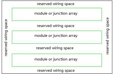
6. telephone
1) multi-line telephone system N+1 line system 2N line system host capacity extension and jack
2)bus-line telephone system independent bus-line telephone system shared bus-line telephone system(can connect with fire alarm system)
line type
host capacity
module,extension and jack
Bus telephone switchboard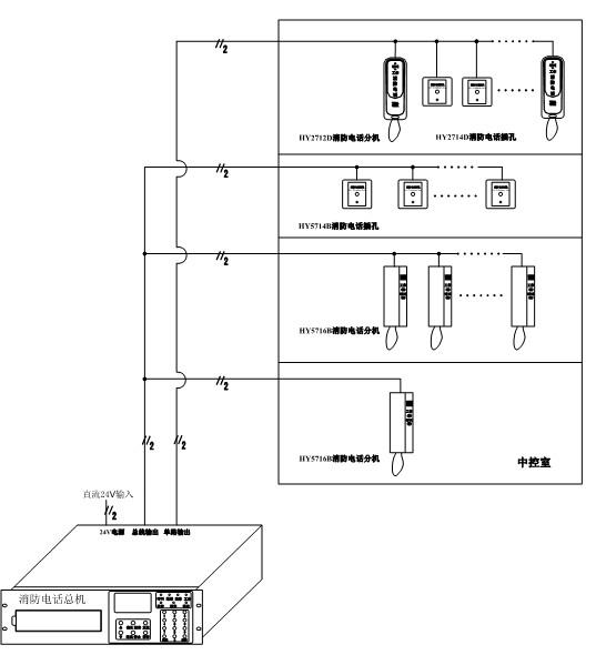
Multi – line telephone switchboard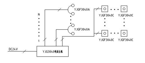
7. broadcast
1) System components: recording plate, regional control panel, power amplifier, module, speaker
Power amplifier power capacity selection:
Capacity can not be less than 1.5 times the maximum capacity of broadcasts in the range of simultaneous broadcasts.
2) system mode: bus system, multi-line system
Bus system broadcast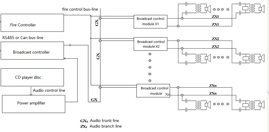
Multi-line broadcast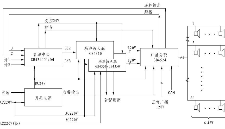
Part 3 Equipment wiring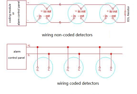
2. manual alarm button
1) non-coded manual alarm button
2) coded manual alarm button
3) with jack and without jack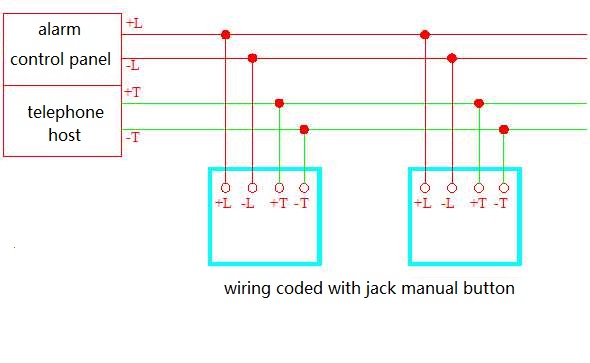
3. fire hydrant button
Fire hydrant button function requirements:Open pump, alarm, lighting
1)non-coded fire hydrant button
2)coded fire hydrant button
Wiring of the pressure switch is similar to that of the non-coded fire hydrant button, just without feedback lighting.
4. Surveillance module equipment connect to surveillance module:
1) Water flow indicator
2) signal valve
3) non-coded fire hydrant button
4) fire damper
5) pressure switch
6) Water level monitoring
7) other feedback signals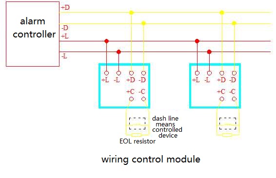
5. Control module equipment connect to control module
1) elevator, floor lights
2) fan, air outlet, air valve
3) fire doors, shutter doors, file smoke hanging wall
4) alarm, sound and light alarm, broadcast circuit
5) rain valve solenoid valve
6) non-fire power cut, emergency lighting
7) other control equipment
6. Combination module The location for the combination
Types of combination modules
1) single input / single output module (each with an address point or share an address point)
2) Dual input module (one or two address points)
3) Dual output module (one or two address points)
4) Dual input / dual output module
5) Three input modules
6) four input / two output modules
7) other combinations of modules module:
1)Single input / single output module – air valve, fire doors, shutter doors, elevators and so on
2)Dual input module – flow indicator + signal valve, monitoring signal concentration
3)Dual output module – non-fire power cut, emergency lighting and so on
4)Dual input / dual output module – shutter doors and so on
5)Three input modules – monitor the signal concentration
6)Four input / two output modules – centralized monitoring and control (eg tower standard layer)
7)Other combinations of modules
7. multi-line control equipment
1) fire pump wiring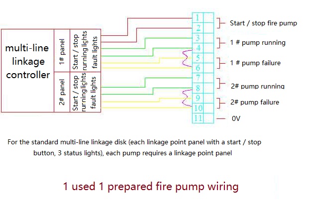
2) smoke exhaust fan wiring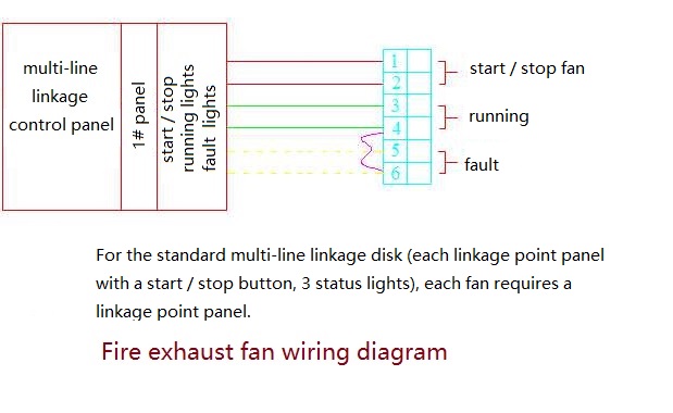
Under normal circumstances, the rain valve group of electromagnetic valve, stage fire screen and other important fire facilities should also be set up multi-line linkage. Note: “Fire Regulations” only require fire pumps and fire engines in addition to automatic control, the need for manual direct control.
Part 4 Fire control center equipment
1. Fire control center equipment introduction
1) fire alarm controller (wall-mounted, cubic up, piano-style)
2) fire alarm controller components (host panel, multi-line disk, bus, circuit cards, communication cards, etc.)
3) DC power supply plate
4) fire broadcast and background music host
5) fire telephone host
6) CRT graphics display system
7) UPS uninterruptible power supply
8) Large space fire gun controller
9) electricity leakage fire alarm host
10) Level display
11) other equipment
2. the fire alarm controller capacity calculation Loop capacity (whether the detector / module is coded differently) Reserve capacity (consider fire partition) Number of loops Combined with multi-line disc,the number of bus lines Controller capacity

