Firstly, The central system failure.
1. The central machine can not receive all users alarm information.
Possible causes: telephone line interference is too large, telephone line noise, telephone line short circuited or open circuited, telephone anti-theft switch is turned on, communication failure of the telecommunications bureau, host alarm center communication programming error, center software serial port closure, serial line connection error, serial damage, the failure of the computer itself may lead to the center machine can not receive alarm information.
Solution: check whether there is a short circuit and open circuit on the telephone line, turn off the anti-theft switch on the telephone, check whether the central communication programming of the user-side host is correct, including (center phone number, center communication level, central communication format, user number, reporting options, etc.); Check if the central software is a trial and query the system logs to check the software expiration period.
2. The center machine received alarm information, but can not pop up on the software.
Possible cause: The user information does not exist in the central software. The serial port is closed, the serial line connection error, the serial port damage may cause the center machine to receive the alarm message, but can not pop up on the software.
Solution: Add user information to the central software, open the corresponding serial port, connect the serial line correctly, check whether the serial line interface is damaged.
3. The central machine received the alarm information, but the alarm information can not be uploaded or downloaded.
Possible causes:the central telephone line interference is too large, the telephone line appears short circuit, open circuit, telecommunications bureau communication failure. Forwarding number in the center software is not filled correctly may cause the center machine to receive alarm information, the alarm can not be transmitted up/down.
Solution: Check whether the telephone line interference is too large, the telephone line has a short circuit, open circuit, correctly fill the forwarding number in the center software.
Secondly, the alarm host system failure.
1. The alarm host is armed or forced to armed and the wired detector is triggered, but the host does not alarm.
Possible causes: Wired detector and alarm host connection line error, line short circuit, open circuit, detector supply voltage is insufficient, end-of-line resistance missed or wrong wired, zone properties are not edited or edited error, etc. may lead to the alarm host does not alarm after the detector is triggered.
Solution: Check the cable connection between the detector and the alarm host. Check whether the end-of-line resistor is not connected or wrong connected. Use the meter to test whether the line is short-circuited, open circuit, detector power voltage is stable (cannot be less than 9V) and so on. If the zone is not correctly programmed, should correct it.
2.The alarm host does not alarm after the wireless detector is triggered.
Possible reasons: wireless detector battery power is low. Wireless detector code is not correct, or messy code is learned into the alarm host. The wireless detector learned into the alarm host is not programmed with zone properties, or zone properties are wrong edited. The distance between the wireless detector and the alarm host exceeds the rated transmission distance. There is metal barrier between the wireless detector and the alarm host.
Solution: replace the battery. Re-code the wireless detector to the alarm host. Program the zone properties of the detector zone. Shorten the distance between the wireless detector and the alarm host. If there is a metal barrier between the detector and the alarm host, then re-adjust the detector installation location.
3.The alarm host can not receive high-frequency signal, why? (including remote control and wireless converter)
Possible causes: The remote control battery is low or the converter is not powered on. The wireless code of the remote control and wireless converter is not learned to the alarm host, or is too far away from the host. The host failure to decode etc.
Solution: replace the battery or change a remote control to test, correctly program to learn wireless code, shorten the distance between the remote control and wireless converter and the host. If multiple remote controls can not be learned into the host, that means the alarm host may have problem of high-frequency reception and need to return to manufacturer for repair.
4.The alarm host false alarm.
Possible cause: The possibility of false alarm caused by the alarm host is very low. Because the host is only a signal receiving processor, and even if there are false alarms, most of them are caused by detectors. Unless the voltage fluctuation is too large may lead to host false alarm. When false alarm occurs, please check the detector status.
Solution: First confirm the false alarm zone and detector, and then check the detector.
5.The alarm host is in normal use but it makes a sound without any reason.
Description: The chimes of the host can be divided into beeps, fault chimes, guard exit delay tones, alarms into delay tones.
Solution: Please confirm what kind of chime the host is making. If there is no any operation on the alarm host, the sound could be a fault detected by the alarm host. Please check further indication of the fault and solve it.
6.The alarm host connects to the external alarm horn, but when alarm goes off, the external alarm horn does not make sound.
Possible causes: the positive and negative wire between the horn and the host is opposite. There is short circuit or open circuit of the host and horn link. The host output voltage is not enough (about 12V). The external alarm horn is not programmed or correctly programmed into the alarm horn.
Solution: Check whether the wire connected to the alarm host and horn is correct. When the host is alarming, test the host’s external alarm interface voltage and it should be 12V or above. If there is no output, that means the external horn is not programmed or PGM output is not open. If the above operation is correct and still no sound from the alarm horn, then please replace a horn and test.
7.The alarm host does not dial telephone phone or mobile phone to notify the alarm.
Possible reasons: telephone line interference is too large, telephone line short circuit or open circuit or telephone anti-theft is turn on. The phone number is not programmed or correctly programmed to the alarm host. (including communication phone number, format, report level such as alarm report, fault report).
Solution: check whether the telephone line interference is too large, check whether the telephone line has a short circuit, open circuit problem exists, confirm whether the connected host’s telephone line needs to dial code before dialing the outside line phone. if need, please enter the code before the telephone number. Otherwise re-program the alarm receiving number correctly.
8.The alarm host does not communicate with service center after alarm.
Possible causes: Large interference of the telephone line caused the failure of data transmission. The host connected telephone line short circuit, open circuit. Programming process wrong of service center communication telephone number, communication format, communication level, user number etc.
Solution: Check whether the telephone line is short-circuited, open circuited. Correctly program the central communication telephone number, the central communication level, the central communication format, the user number. If all of the above is normal large telephone line interference maybe the cause. The central communication is a data transmission, different from the general voice transmission, if the telephone line interference is too large it will lead to unreliable communication. The engineer can do the following process to tests.
1.Listen to the telephone receiver, if there is a significant noise, you should find the communication company to solve it. Because the telephone line interference will cause the alarm host data transmission error.
Use a multimeter DC voltage range to test the following parameters for telephone lines
a. Empty voltage: When the telephone handset is not picked up, measure the DC voltage on the telephone line to see if it is 43 to 53 volts.
b. Pick up voltage: Pick up the telephone handset, measure the voltage on the telephone line, to see if it is 6 to 10 volts.
C. the resistance voltage: Parallel a 300 ohm resistor on the telephone line, measure the DC voltage on the telephone line to see if it is 6 to 12 volts.
After testing, do the following based on the test results:
a. If all the voltages tested meet the requirements, the line is OK and the alarm host should be replaced for a try. (The replacement alarm host must has been actually tested to the center communication and is very reliable, otherwise it may cause misjudgment)
b. If the voltage is not normal, but deviation is not much, you can series a 100, 200 or 300 ohm (1/4 watt) resistor on the telephone line to try it;
c. If the voltage is not normal and exceeds too much, or if the test according to B method does not solve the problem, please send the host back to our company together with the parameter records of the test. Our technical engineers will specifically modify the host circuit parameters according to the user’s phone line parameters to accommodate the telephone line.
Thirdly, detector failure
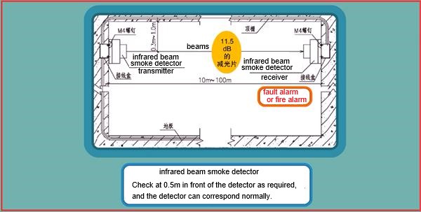
1. Beams
a. After the infrared beam is connected to the host and the host is armed, trigger the beam, but the alarm host does not alarm.
Possible causes: there are blocks between the two beams; the beam and the host connection is wrong; the beam tamper switch is not closed; the line has a short circuit, open circuit, insufficient supply voltage, beam zone properties are not programmed correctly.
Solution: correctly connect the line and end resistor between the beam and the alarm host (the connection and size of the resistor depends on the host used), check the line for short circuits, open circuit, test whether the power supply voltage of the beam is larger than 9V, check whether the alignment light on the transmitter end is off. Flashing or long light of the transmitter is not normal, reprogram the beam’s zone properties correctly.
b. During the initial installation and debugging of the beams, the alarm goes off when the alarm host is disarmed.
Possible cause: The beam is with open circuit and the zone property is set to a 24-hour zone.
Solution: Check the beam circuit and correctly connect it.
c. Why is the alignment light of the beam flashing or keeping on?
Possible causes: the synchronization wire connection is wrong, the receiving end and the transmitter end are not aligned, the receiving end and the transmitting end distance is too far, there are blockers in the detection area, the supply voltage is insufficient, the receiver’s tamper switch is not closed.
Solution: Correctly connect the synchronization wire; Check whether the tamper switch is closed; Adjust the angle between the receiving end and the transmitter to align it; Ensure that the supply voltage is above 9V.
d. The beam false alarm
Possible causes: the power supply voltage floating up and down too large, environmental causes. Intermittent short circuit caused by wire flooding.
Solutions: Ensure that the supply voltage is above 9V; Check whether the wiring is normal. Replace the false alarm beam with the correctly working alarm beam to check whether there is environment interference.